In the same manner as for PipeStart, there are several ways of ending a pipe. It is important that pipe start is correct, but it is just as important to end the pipe correctly. You can end a pipe in the following manners:
-End freely, in this case you often want to connect to the pipe end later
-End with connection to object or other pipes
-End in the storey above or below.
-End with a symbol or with sprinkler head
If you press the button Escape on your keyboard, the pipe is ended freely. You can on a later occasion connect to this end and continue the pipe.
If SmartSnap is active, and you draw a pipe near a connection point of the same type, DDS-CAD will suggest that you connect to this point. This point could be an object, another pipe with the same medium, another bend with the same medium or another tee with the same medium. You will, for instance, not be able to connect a cold water pipe to a sewer pipe, or a hot water pipe to a cold water pipe. Flexible pipes, such as pipe in pipe, or underfloor heating pipe, cannot be connected, as tees are not used here. If you want to connect to a point suggested by DDS-CAD, then point at the point with the cursor and press the left mouse button once. If there are a difference in height (different Z assembly height) on your pipe and the connection point, DDS-CAD will make a number of suggestions for how to connect.
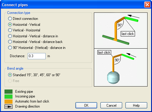
Different ways of connecting pipes to the connection point.
Direct connection: By difference in height, DDS-CAD will calculate the slope needed for a direct connection. Mostly used for sewer pipe/pipes under ground
Horizontal- Vertical: Pipe is extended horizontally until it is directly above or below the connection point and then connected vertically
Vertical-Horizontal: Pipe is extended vertically from the last mouse click to the height of the connection point, and then horizontally to the point
Horizontal-Vertical-distance in: Pipe is extended horizontally until a certain distance (entered in the distance field) from the connection point, then lead vertically to the same height as the connection point, and then horizontally until reaching the point.
Horizontal-Vertical-distance back: Pipe is extended horizontally past a distance (entered in the distance field) to the connection point. Then lead vertically to the same height as the connection point and then horizontally until reaching the connection point.
90 degrees – Horizontal – (vertical) distance in: Make a parallel line from the last point along the point to be connected, then horizontally to a distance from the connection point, vertically and into the connection point.
The connection from one sewer pipe to another will automatically insert a 45 degree tee. If the sewer pipe has been drawn with a slope, DDS-CAD will find out which way the tee should point. Likewise, if the connection is non-orthogonal with another pipe, DDS-CAD will presume that you want the tee in the same direction as the direction in which you entered. If you insert a sewer pipe without slope and hits 90 degrees on the pipe, DDS-CAD will ask which way the tee should point.
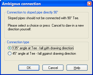
For sewer pipes without slope and with 90 degree connection, DDS-CAD will ask which way the tee is to point.
If this is to function, it is important that the ghost files (architectural files) are exactly on top of each other, that the storey height is correct and that the numbering of storey numbers is correct.
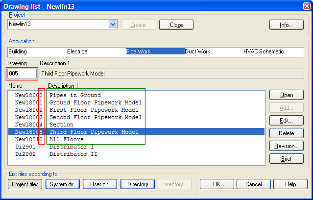
Example of badly planned storey building.
If the storey numbering is not correct, the risers will not function. On the image above you will see that the storey numbers (red rectangle) do not correspond with the storey descriptions (green rectangle). In this case you would get problems if you wanted to connect risers between the 2nd and 3rd floor, as a section drawing is lying in between. Therefore, take the time to make a thorough plan how the building of storeys is to be done before creating models.
You can end a pipe in another storey in the following manners:
While the pipe drawing is active, click the right mouse button and end in the storey above or below from the pop-up menu.

Click to see a video
Start from the first floor, select the function key AutoDraw. Typical example for shafts.
Click to see a video
Start from object with a fixed connection point, either up or down (example of this is a drain with bottom outlet, toilet), and press the button Autodraw.
Click to see a video
Start from the tee/pipe end pointing either up or down, and press the button Autodraw.
Click to see a video
< Previous Section - Next Section >